Program Design
IS 436 — Chapter 10
What We're Learning
This chapter = how to build that game plan.
- Turn a logical diagram into a physical plan with real tech details
- Draw a structure chart — a map of every program piece
- Write a program spec — instructions for each piece
- Use pseudocode — plain-English logic steps (no coding language needed)
- Understand event-driven programming — programs that react to things that happen
Logical vs. Physical — What's the Difference?
Answers: "What does the system do?"
Like a restaurant menu —
it lists "Burger, Fries, Soda"
but says nothing about how they're made.
Answers: "How will we build it?"
Like the kitchen recipe —
exact ingredients, cooking steps,
who grills and who assembles.
Physical says "INSERT CustomerID (int), Email (varchar 100), SignupDate (date) into the MySQL Customers table."
The Physical Model — 3 Things It Adds
Example "We use PostgreSQL on Amazon RDS" instead of just "data store"
Example Phone number →
(###) ###-#### |
Price → decimal(10,2) |
Date → YYYY-MM-DD
Example 🧑 Cashier scans items (human step)
🖥️ System looks up prices and calculates tax (automatic step)
A dotted line on the diagram separates the two sides.
Physical DFD — Simple Rules
Keep every shape from the logical DFD. Just add details on top.
Example "order info" becomes "OrderID, CustomerID, ItemList, TotalPrice, OrderDate"
Example Add a "Write to Error Log" step that runs every time a payment fails — this wasn't in the logical DFD.
Example "Verify Age" → handled by the AgeVerification microservice, not a human
5 Steps to Build the Physical DFD
Write the person's name or system name inside or next to each process bubble.
Example "Process Payment" → Stripe API (automated)
A dotted line: everything above = human, everything below = computer.
Example Customer fills form (human) → system saves it (computer)
Error logs, temp files, session tracking — invisible to users, essential for developers.
Example "user info" → UserID (int), Username (varchar 50), PasswordHash (char 64)
Record every change so the whole team uses the same definitions.
Side-by-Side: Logical vs. Physical DFD
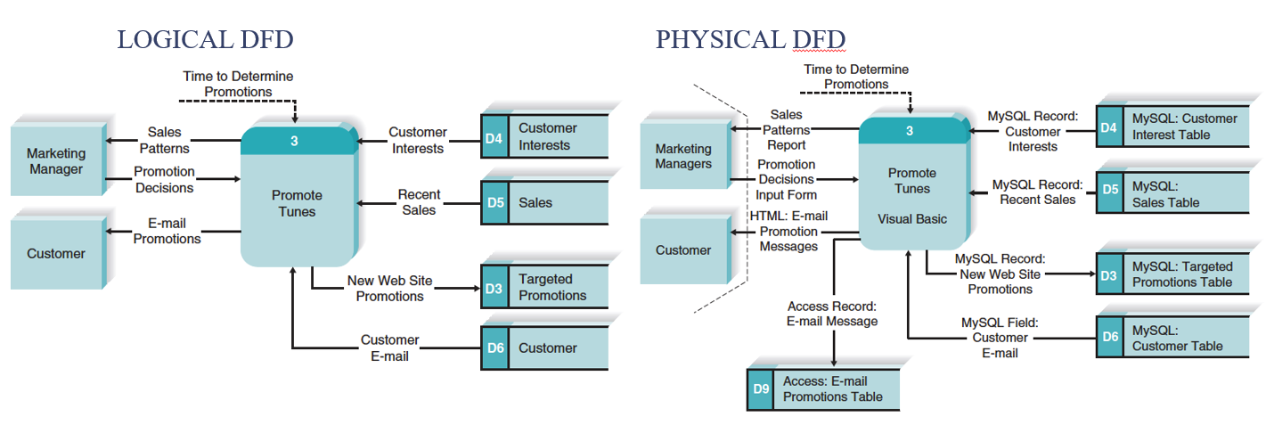
Left = logical (what the system does). Right = physical (how it's built). Spot the new labels, dotted boundary line, and exact field names on the right.
Designing Programs
After the physical DFD is done, the analyst designs how each program module will work.
① Top-down, modular approach → ② Structure chart → ③ Program specifications
Top-Down, Modular Approach
Start with the big picture. Keep breaking it into smaller pieces until each piece does exactly one thing.
Level 1: Place Order
Level 2: Validate Cart | Charge Card | Send Confirmation Email | Update Inventory
Level 3 (under Charge Card): Check Card Details | Contact Bank | Record Transaction
If the email module breaks, the payment module still works fine.
The Structure Chart
A diagram that shows all program modules arranged like a family tree — who calls who, and what data is passed.
A company org chart.
CEO = top module (controls everything)
Managers = mid modules (coordinate)
Workers = bottom modules (do the actual work)
Sequence — do A, then B, then C
Selection — if discount? yes/no
Iteration — repeat for every item in the cart
Structure Chart — Example
Top box = the main controller. It calls the boxes below it. Those boxes call the ones below them. Labels on arrows show what data moves between boxes.
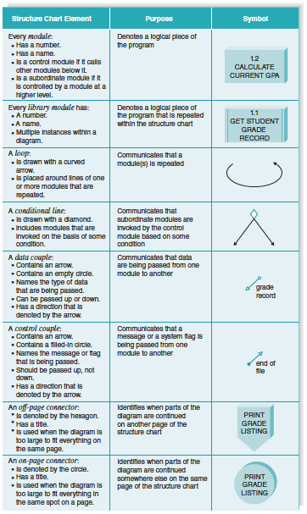
What Do the Symbols Mean?
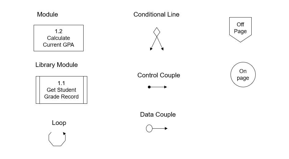
e.g., "Calculate Tax"
Parent always calls child — never the other way
e.g., "cartTotal" flows down to "ApplyDiscount"
e.g., "paymentOK = true" sent back up to parent
e.g., only call "SendSMS" if phone number exists
e.g., repeat "ProcessItem" for every item in cart
How to Build a Structure Chart — 4 Steps
Example "Process Online Order" is the top box.
Example "Process Online Order" → "Validate Cart" + "Charge Payment" + "Send Email" + "Update Stock"
Example "Process Order" calls "Charge Payment."
"Charge Payment" does NOT call "Process Order."
Example Going down: cartItems, customerID | Coming back up: paymentSuccess (true/false)
Design Quality #1 — Cohesion
Cohesion = is each module focused on one job?
High cohesion = good. Low cohesion = bad.
One module called "HandleEverything":
• validates the login form
• sends a welcome email
• saves to the database
• generates a PDF receipt
If the email breaks, it might take down the whole login. Impossible to test one piece at a time.
Four separate modules:
• ValidateLoginForm()
• SendWelcomeEmail()
• SaveUserToDatabase()
• GeneratePDFReceipt()
Email breaks? Fix only that module. The others keep working.
Design Quality #2 — Coupling
Coupling = how much do modules depend on each other?
Loose coupling = good. Tight coupling = bad.
PrintReceipt() goes into the database itself to get the order data.
If the database table changes, PrintReceipt() breaks — even though printing has nothing to do with the database structure.
ProcessOrder() fetches the data, then passes only what PrintReceipt() needs:
orderTotal, itemList.Now you can change the database however you want — PrintReceipt() never notices.
Design Quality #3 — Fan-In & Fan-Out
High fan-in = good — that module is being reused a lot!
Example FormatCurrency() is called by the Cart page, the Receipt page, and the Admin Dashboard.
One module. Three places. Zero duplication.
Keep fan-out ≤ 7. More than that = the module is doing too much.
Example "ProcessOrder" that calls 10 sub-modules is too complex.
Fix: split it into ValidateOrder() (calls 4) + FulfillOrder() (calls 5).
Structure Chart Quality Checklist
- Reuse modules wherever possible — write it once, call it from many places.
Bad: copy-pasting the same email logic into 4 modules. Good: one SendEmail() module called by 4 modules. - Aim for high fan-in — shared utility modules should be called by many.
- Max 7 children per module — if a module calls 10 others, split it up.
- One job per module — if you can't name it in 3–4 words, it's doing too much.
- Pass only what's needed — don't send 20 fields when the module uses 2.
e.g., don't pass the whole customer object to PrintReceipt() if it only needs customerName. - Use what you receive — if a module gets a value, it should actually use it.
- Flags flow upward — a child tells the parent "success/fail," not the other way.
e.g., CheckStock() returns "inStock = true" up to ProcessOrder(). - Each module has a reasonable size — not 1 line, not 500 lines.
Program Specifications — What Are They?
After the structure chart, you write a detailed instruction sheet for every single module.
The program spec is the instruction sheet for each apartment — what appliances go where, how the wiring works, what each switch does.
But all good specs cover the same 6 things (next slide).
What Goes in a Program Spec?
| Section | Simple question it answers | Example |
|---|---|---|
| Module Info | What is this module called? | Name: ValidateLogin | Language: Python | Author: A. Chen |
| Trigger / Event | When does this run? | Runs when the user clicks the "Log In" button |
| Inputs | What data comes in? | username (text, max 50 chars), password (text, max 100 chars) |
| Outputs | What does it return? | loginSuccess (true/false), errorMessage (text) |
| Pseudocode | What is the step-by-step logic? | Written in plain English — next slides |
| Special Rules | Any business rules? | Lock the account after 5 failed attempts |
What is Pseudocode?
Pseudocode = plain English logic.
It's not a real programming language. It's the thinking written out before coding starts.
You focus on the logic, not semicolons and brackets.
A Python dev and a Java dev can both read the same pseudocode and build the same thing.
BEGIN / ENDIF / THEN / ELSE / ENDIFWHILE / ENDWHILEFOR EACH / ENDFORREAD / WRITECALL / RETURNIndent each level. Indentation = structure.
Pseudocode Example: User Login
READ username, password
IF username is empty OR password is empty THEN
WRITE "Please fill in all fields"
RETURN loginSuccess = FALSE
ELSE
CALL CheckDatabase(username, password)
IF match found THEN
WRITE "Welcome, " + username
RETURN loginSuccess = TRUE
ELSE
ADD 1 to failedAttempts
IF failedAttempts >= 5 THEN
WRITE "Account locked — too many attempts"
ENDIF
RETURN loginSuccess = FALSE
ENDIF
ENDIF
END ValidateLogin
No real code. Just logic. Any programmer can turn this into Python, Java, C# — whatever the project uses.
Pseudocode Example: Shopping Cart Total
READ cartItems, isMember
SET total = 0
FOR EACH item IN cartItems
SET total = total + (item.price × item.quantity)
ENDFOR
IF isMember = TRUE THEN
SET total = total × 0.90 ← 10% member discount
ENDIF
WRITE "Your total: $" + total
RETURN total
END CalculateCartTotal
FOR EACH = iteration (loop). IF = selection (choice). Together inside one module = high cohesion — this module does one job: calculate the total.
Textbook Pseudocode Example
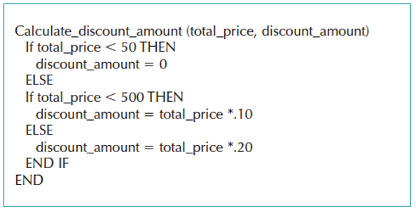
Notice the indentation — it makes nesting clear at a glance, just like real code.
Full Program Specification (Textbook)
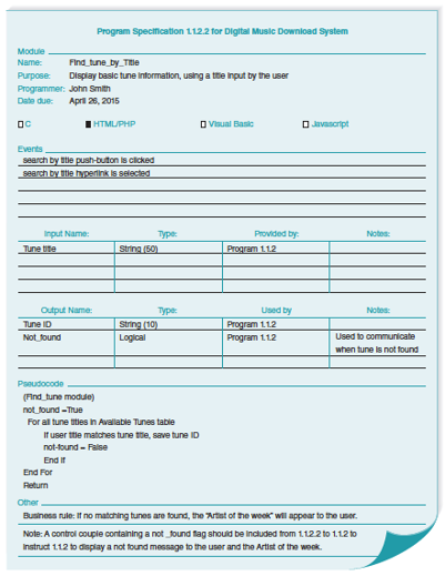
One document = module info + trigger + inputs/outputs + pseudocode. Programmers use this to write the code.
Event-Driven Programming
Most programs don't run from top to bottom. They wait… then react when something happens.
It listens 24/7. The moment it detects smoke (event), it triggers the alarm (handler).
Your app works the same way.
• User clicks a button
• A timer goes off
• A file arrives
• A database record changes
It sits idle until the event fires.
Then it runs automatically.
Your program spec must say: "This module runs when ___."
Event-Driven: Real App Examples
| What happens (Event) | Triggered by | Module that runs (Handler) |
|---|---|---|
| User clicks "Place Order" on Amazon | Button click | ValidateAndSubmitOrder() |
| Uber driver accepts your ride | Driver taps "Accept" in the app | NotifyRider() + StartLiveTracking() |
| Credit card is declined | Bank returns "failed" response | ShowErrorMessage() + LogFailedAttempt() |
| Netflix auto-plays next episode | Timer fires at end of credits | LoadNextEpisode() |
| Product goes out of stock | Inventory drops to 0 (DB trigger) | SendRestockAlert() + HideAddToCartButton() |
Every row = one event + one handler. Your program spec documents this "when X happens, run Y" relationship for every module.
Chapter 10 — Full Workflow
Example "Store Order" → "INSERT OrderID, CustomerID, TotalPrice into MySQL Orders table"
Example "ProcessOrder" calls "ValidateCart", "ChargeCard", "SendEmail", "UpdateInventory"
Example Spec for "ChargeCard": triggered by order confirmed; input: cardToken, amount; output: chargeSuccess (true/false)